Calculator
- Home
- Transformers
- _What is Transformers?
- _Top 10 Transformers In India
- Electrical genrating Plants
- _Hydro Power Plant
- _Biomass Power Plant
- _CHP Plant
- _Fossil Fuel Plant
- _Thermal Power Plant
- _Solar Power Plant
- Generator
- _Top 10 generator
- _Genrator Price
- _DC Generator
- Invention & Laws
- _Light Bulb Invention
- _Faraday's Law of Induction
- _Faraday's Law of Electrolysis
- _Fleming Right hand rule
- _Joule's Law of Heating
- _Ohm's Law of Conduter
- _Lenz's Law of electromagnet
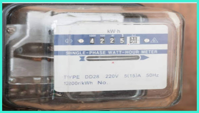
How to work electronic meter?
How to work electronic meter?
It is designed to measure kWh, and to do so it measures
Voltage (Across Incoming Line)
Current (probably only in one leg, as the other would be symmetric with it)
Phase (offset between voltage sine wave and current sine wave)
Cable suitable for measuring current has to physically pass through a part of the equipment - usually a current transformer is placed around the current-carrying conductor. The most convenient designs have four large connection terminals - two in and two out (some more in 3-phase meters, of course) to make wiring operations easier. One can think of the meter as a black box in series with the supply, if that helps.
The instrument starts by continuously measuring the instantaneous power, using the calculations:
Power = Voltage × Current × Cosine (θ)
where is the phase offset measured between the two waves.
To convert this to kWh (which we pay for) the instantaneous power is integrated over time - for a static load that simplifies to kW x time, of course.
The resulting kWh is then stored in a non-resettable totalizer for display to the meter reader (or, in the case of smart meters, transmission to the supplier).
Mechanical meters used a pair of wound coils to drive a rotating wheel, one for voltage, one to drive a rotating wheel whose speed was the product of the two measurements, and one to measure actual power. Automatically ignored the reactive component. That wheel moved to a gear train that completed the revolutions.
Most Popular
Categories
- 10 kVA Stabilizer (1)
- Alternator (3)
- Ampear (1)
- Armature (1)
- Battery (1)
- Biogas (1)
- Biomass (1)
- Boiler (1)
- Bulb Thomas Alva Edison (1)
- Capacitors (1)
- Cogeneration (2)
- Conductor (1)
- Contractor (1)
- Crankshaft (1)
- DC Generator (1)
- Diesel Generator (2)
- Diodes (1)
- Earthing (1)
- Electric Meter (1)
- ElectricIan Tools (1)
- Electricity generation (1)
- Electricity Saving Tips (1)
- Electrolysis (1)
- Electromotive force (1)
- Electron (1)
- EMF (1)
- Faraday's law (2)
- Fleming rules (1)
- Fossil Fuel (1)
- Fuse (1)
- Generator (2)
- Heater (1)
- Hydropower (1)
- Ic (1)
- Incandescent Bulb's Law (1)
- Inverter (1)
- Joule's Law of Heating (1)
- Kirchoff current law (1)
- Kirchoff Voltage Law (1)
- Kirloskar Generator (1)
- Lenz law (1)
- Lighting Arrester (1)
- Magnetic Field (1)
- MCB (2)
- Motor (1)
- Multimeter AC and DC Measuring tools (1)
- Nuclear Power plant (1)
- Ohm's Law (1)
- Power Factor (1)
- RCB (1)
- RCBO (1)
- RCCB (1)
- Rectifier (1)
- Relay (1)
- Resistor (1)
- Resistor in series Resistor in parallel Resistor formula Resistor calculator Resistor problem (1)
- Servo Stabilizer (1)
- Short circuit Circuit breaker (1)
- Solar Energy (1)
- Star delta (1)
- Thermal Power (1)
- Tidal waves Power (1)
- TOP 10 Cable (1)
- Transformer (2)
- Turbine (1)
- Windmill (1)
Popular Post
Labels
- 10 kVA Stabilizer
- Alternator
- Ampear
- Armature
- Battery
- Biogas
- Biomass
- Boiler
- Bulb Thomas Alva Edison
- Capacitors
- Cogeneration
- Conductor
- Contractor
- Crankshaft
- DC Generator
- Diesel Generator
- Diodes
- Earthing
- Electric Meter
- ElectricIan Tools
- Electricity generation
- Electricity Saving Tips
- Electrolysis
- Electromotive force
- Electron
- EMF
- Faraday's law
- Fleming rules
- Fossil Fuel
- Fuse
- Generator
- Heater
- Hydropower
- Ic
- Incandescent Bulb's Law
- Inverter
- Joule's Law of Heating
- Kirchoff current law
- Kirchoff Voltage Law
- Kirloskar Generator
- Lenz law
- Lighting Arrester
- Magnetic Field
- MCB
- Motor
- Multimeter AC and DC Measuring tools
- Nuclear Power plant
- Ohm's Law
- Power Factor
- RCB
- RCBO
- RCCB
- Rectifier
- Relay
- Resistor
- Resistor in series Resistor in parallel Resistor formula Resistor calculator Resistor problem
- Servo Stabilizer
- Short circuit Circuit breaker
- Solar Energy
- Star delta
- Thermal Power
- Tidal waves Power
- TOP 10 Cable
- Transformer
- Turbine
- Windmill


0 Comments